Selection principle of sheet metal materials.
Fundamentals of sheet metal design.
The blackstone fundamentals of sheet metal design sheet metal design is key to the production of quality products.
We would like to show you a description here but the site won t allow us.
Sheet metal fabrication is the process of forming parts from a metal sheet by punching cutting stamping and bending.
When a sheet metal design has small holes it requires smaller punches during operation.
The minimum hole diameter should be equal to or more than the sheet thickness.
Unlike general purpose cad tools solid edge includes sheet metal specific features like emboss dimple drawn cut bead contour flange straight brake and etch.
Understanding the comprehensive performance of materials and the correct material selection have an important impact on product cost product performance product quality and processability.
Sheet metal can be cut bent and stretched into an amazing array of shapes.
Distance from the bend to the hole edge should be equal to or more than twice the thickness of the sheet.
Sheet metal materials are the most commonly used materials in the structural design of communication products.
The components can be brushed plated anodized powder coated spray painted silk screened or otherwise marked.
3d cad files are converted into machine code which controls a machine to precisely cut and form the sheets into the final part.
Hardware can be inserted into sheet metal components.
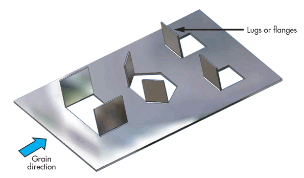
Bend relief refers to an indentation that designers should make on sheet metal designs so that the.
To meet unique sheet metal design challenges like manufacturability solid edge streamlines the entire sheet metal product development process from cad design through flat pattern and drawing development.
While the design can guide you to speci c materials the materials themselves can often lead to functionality and cosmetic improvements based on performance characteristics of the chosen metal alloy.
Few thumb rules or sheet metal design fundamentals.
When designing with sheet metal there is a relationship between the design of the part the use of the part and the choice of material.
Sheet metal is cut stamped punched sheared formed bent welded rolled riveted drilled tapped and machined.